
五部门关于开展2024年新能源汽车下乡活动的通知
过度到42V电池无皮带引擎
来源:新能源汽车网
时间:2016-06-28 13:04:10
热度:
过度到42V电池无皮带引擎摘要:为了满足增加功率的需求,汽车制造商把汽车电池的电压从目前的14V增加到大约42V.40年前汽车制造商把电池电压从6V系统增加到14V,主要是出于功率
摘要:为了满足增加功率的需求,汽车制造商把汽车电池的电压从目前的14V增加到大约42V.40年前汽车制造商把电池电压从6V系统增加到14V,主要是出于功率的考卷.从那以后,汽车的电功率消耗增加了50%以上.下一代的汽车将有更多的电子设备而消耗更多的功率,超出14V所能提供的3KW的极限.而42V系统将会提供大约8KW的功率,从而能满足更高功率的需求.此外,42V系统还有其它的好处……
Making the transition to 42V electrically-powered 'beltless engines'
If it comes, transition to 42V electrically-powered beltless engines will be difficult, but presents opportunities to engineers
By Qi Wang, Keithley Instruments
To meet increasing electrical power demands, automakers are moving to increase vehicle battery voltage from today's 14V to approximately 42V. It's been more than 40 years since car makers switched from the standard 6V system - a change triggered by similar power considerations.
Since then, vehicle electrical power consumption has increased by more than 50 percent. Next-generation cars will have even more electronics and require a power source with an output of more than 3kW, the limit of today's 14V system. A 42V system will deliver around 8kW and allow better management of the higher power requirements.
A 42V system sets the stage for advanced technologies that will allow a switch from mechanical belt-driven systems to electrically-powered ones. Possibilities
include electric power steering, electromechanical brakes, electrical HVAC systems, electromagnetic valve trains, integrated starter-generators and electronic ride control systems.
The so-called "beltless engine" of the future will be another reason for lower weight packaging (because accessories can be located outside the engine compartment), leading to higher efficiency that improves gas mileage and reduces emissions.
Before 42V systems can be adopted widely, many engineering problems must be addressed, including the engine/electrical system architecture and a migration strategy (dual 14/42V systems vs. straight 42V systems). Short-term challenges associated with dual voltage systems include more wiring, extra weight and added complexity.
Regardless of migration path, suppliers need time to develop new components and a part identification system that distinguishes between 14V and 42V parts.
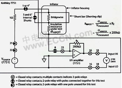 Figure 1. The test system includes voltage and current sources integrated with measuring instruments and a switching matrix. |
Electrical and electronic components evaluation
While 42V is not far from 14V in physical terms, real-world issues are a cause for concern. Current 14V designs won't automatically work at 42V; even simple fuses will not migrate, let alone dimmers and active load controllers. Some fuse panel and harness makers have found that common 14V mini- and maxi-fuses do not behave properly at 42V.
They can fail to interrupt excessive currents properly, causing serious overload conditions. Also, interconnection technologies have evolved for optimal cost and performance in a 14V environment. The present design of connectors, circuit breakers and relay contacts may not be optimal at 42V.
Therefore, manufacturers must re-evaluate component suitability for the higher voltage. Tests can range from simple continuity tests to full electrical characterization of a component's functional performance at 42V.
Reliability Issues
At 42V and higher power levels, many components, such as wires and relays, experience electrical stress three times higher than before. With higher stress, components tend to break down more often. Therefore, component and module manufacturers have to perform more reliability testing, such as burn-in and accelerated stress tests, to ensure adequate service life.
Safety Considerations
Safe distribution of 42V power throughout a heavily optioned automobile is also a challenge. In the first place, the 42V standard was established because higher voltages create human safety issues. For example, 50V can stop a human heart, and anything higher than 60V requires more heavily insulated wires and connectors, which add weight. To prevent fires, electrical distribution designs must allow for jump-starting at the higher voltage and provide protection if battery connections are reversed.
Component, conductor arcing problems
Relay, switch and conductor arcing is another problem that must be addressed; its potential for serious damage is greatly increased in 42V systems. Recent research shows that 42V arc energy is 50 to 100 times higher than in a 14V system.
Such arcing can generate temperatures of up to 982.22°C, ignite fuel vapors, start a fire in plastic insulation, and even melt metal. Simply redesigning relays, switches and fuses for higher voltage, and using flame-retardant materials is not a total solution-these component designs should suppress arcs.
The same is true for other connections, particularly those that could be opened during replacement of fuses, batteries and other components. Mechanical design features must ensure that electrical terminals are correctly seated and locked. Therefore, increased use of clips, clamps and shields may be required.
The impact of 42 volt systems
Implementation of 42V systems will affect the design, manufacturing, assembly and testing of most electrical and electronic components. Electromechanical components such as alternators, motors and starters may require more time on field coil-winding machines to get the same number of ampere-turns (given that the current and wire gauge will be one-third of what it was for 14V devices).
Other components will be redesigned or replaced. In many cases, suppliers will be asked to make them lighter, more efficient and less expensive. This probably means that semiconductors will replace electromechanical designs in some switch and relay applications. This will call for higher power devices, such as trench MOSFETs in higher voltage packages.
While basic designs of existing assembly and test equipment should be adequate for 42V components, the higher voltage will require some modifications. For instance, additional production testing may be required to verify arc suppression and EMI/EMC compliance.
To design the new 42V components properly, car makers and their suppliers must understand critical engineering and performance issues. As a result, there will be increased R&D activity involving the electrical characterization of devices and their designs.
Typically, this entails electrical measurements under various load conditions, insulation resistance and hi-pot testing, and very low resistance measurement of relay contacts and connector terminals.
Simplifying, speeding up measurements
Many 42V tests will require only common instruments, such as load banks, high current power supplies and DMMs. More specialized tests of conductors and insulators require instruments designed specifically for the measurement extremes involved in low-resistance, high-resistance and low-current testing.
Complex devices, such as DC/DC converters, inverters, airbag igniter systems and other electronic controllers require more extensive testing and multifaceted test systems.
Many of these devices contain large numbers of conductor pathways, have many sensor inputs (e.g. temperature, vibration and humidity) and require multiple measurements. Thus, signal switching systems are a valuable test tool. Matrix switches support fully automated testing, reduce the number of instruments required, simplify test procedures and reduce test time.
In such a test system, the measuring instruments, signal switching and other critical components should be selected for ease of integration and optimum overall performance. Better still, the use of a fully integrated data-logging and switch system eliminates the need to integrate many of the test system components.
Application specific measurements
Many automotive electrical tests are essentially resistance measurements to verify continuity or low leakage currents during hi-pot testing. Nevertheless, production testing may dictate multiple measurements in a specific sequence to check for proper assembly and wiring, which creates complexity in simple resistance measurements.
For instance, the electrical check on a vehicle's primary airbag inflator verifies proper characteristics in the pyrotechnic initiator, a fusible wire with a typical resistance of about 2-3 ohms. A second test checks the safety shorting clip to verify that initiator pins are shorted together, a safety feature that prevents accidental activation during airbag handling and installation.
The shorting clip is removed after installation is complete. A third test is a high voltage isolation resistance measurement to ensure that no electrical leakage path (i.e. low resistance) is between the initiator and the grounded metal housing of the system's electronic module, which otherwise could cause a "no-fire" condition. Some manufacturers perform additional electrical tests on their airbag modules and wiring harnesses using the same test stand.
Often, developing such a system from individual instruments and switching components, and then implementing it on the production floor can be quite costly. When available, an application-specific test system can save the user time and money by providing tightly integrated components in a single ready-to-run unit.
Figure 1 above illustrates an airbag inflator hi-pot electrical test circuit using such a system. The test system includes voltage and current sources integrated with measuring instruments and a switching matrix.
The need for Ethernet-based test solutions
The switch to 42V systems will be on a "fast track," so test data sharing across the enterprise will be important. Today, that often means feeding data to multiple departments across an Ethernet bus (Figure 2, below). Having Ethernet-ready instruments with tightly integrated measurement and switching functions greatly simplifies this task.
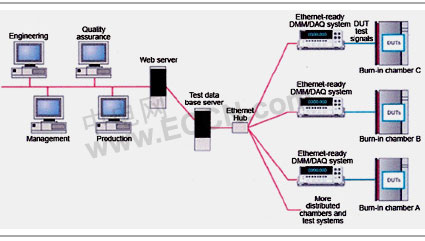 Figure 2. Burn-in chambers may be located in either R&D or production departments and may include vibration. |
An additional benefit of Ethernet-based measurement solutions is that test engineers don't have to trade measurement accuracy for convenience and cost-effective data collection. While PC plug-in cards provide low cost, measurement quality is usually much lower than that available with benchtop instruments.
When the benchtop instrument also has an Ethernet-ready interface, test engineers get the best of both worlds. This becomes increasingly important in a production environment with many test stations or multipoint sensors. In such cases, it's often more cost-effective to use an Ethernet-based instrument than to install multiple PC-based plug-in card systems.
Conclusion
once the transition to a 42V power architecture is completed, wire gauges will be reduced, cable bundles will shrink, smaller connectors can be used and wiring weight will drop. Cable and labor costs will be reduced due to simpler installation.
Full benefits of the new architecture will include increased electrical power for cellphones, GPS units and audio systems, reduced size and mass of motors and other accessories, more flexible and lighter weight packaging, more efficient operation (improved fuel economy and lower emissions), the potential for redundant power sources, faster temperature change in the HVAC system and longer service life for many components and assemblies.
Qi Wang has served as lead applications engineer and currently is involved in product marketing at Keithley Instruments. Dr. Wang has more than 15 years experience in semiconductors, optical physics, and DC and RF measurements. He received a Ph.D. in physics from Texas A&M University and a B.S. in physics from Beijing Normal University.
From
http://www.automotivedesignline.com/howto/197005824;
jsessionid=UOTARMTQH0CHUQSNDLPCKH0CJUNN2JVN
来源:零八我的爱

-
燃料电池电动汽车的缺点2023-11-30
-
燃料电池汽车工作原理2023-11-30
-
燃料电池汽车特点2023-11-30
-
燃料电池汽车关键技术2023-11-30
-
中国氢燃料电池汽车落后国外5—10年2023-11-30
-
通用氢燃料电池汽车有望提前量产2023-11-30
-
燃料电池车,是在侮辱谁的智商?2023-11-30
-
电动车的生机远远大于燃料电池汽车2023-11-30
-
燃料电池客车最有希望率先商业化2023-11-30
-
“十三五”电动汽车展望 电池决定发展重点2023-11-30
-
燃料电池汽车前景如何2023-11-30
-
智能型铅酸蓄电池充电器的设计与实现2016-06-28
-
镍镉电池充电器(九)2016-06-28
-
阀控式密封铅酸蓄电池的均衡充电原理2016-06-28
-
解析48V锂离子电池系统的关键技术及应用现状2016-06-28